Bay Window Macros
Three Sided Bay Window Macro ![]()
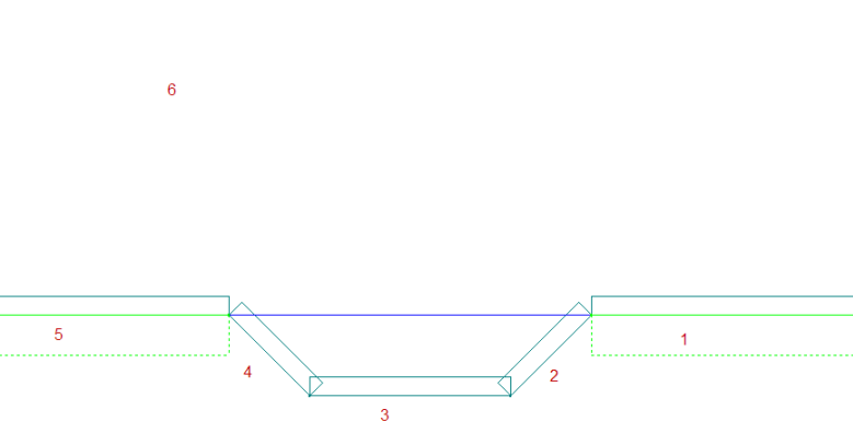
First create intersecting and bay window walls in your layout. Next, select the Three sided Bay Window Macro from Macro Menu--> Roof Planes--> Three Sided Bay Window
Basic steps to follow after starting the macro are as follows:
Select Walls and Back Plane
- You are prompted to select, with your mouse button, the Right intersecting wall
- You are prompted to select, with your mouse button, the Right bay angle wall
- You are prompted to select, with your mouse button, Face bay wall
- You are prompted to select, with your mouse button, the Left bay angle wall
- You are prompted to select, with your mouse button, the Left intersecting wall
- You are prompted to select, with your mouse button, the Back plane (The selected plane must have a baseline that is parallel to the front wall of the bay)
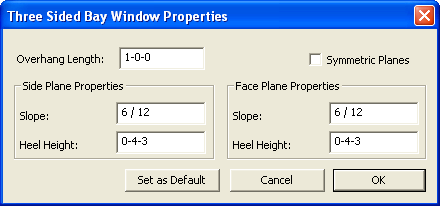
Plane and Overhang Properties
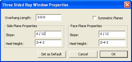
Overhang Length - This is the overhang length around the bay. This value is needed to calculate the angle plane of the bay and to draw in the overhangs.
Symmetric Planes - Check symmetric planes, if the Side and Face Plane Properties are the same values. Please note that it is the your responsibility to match the back plane heel height or calculate the correct heel height to match the back plane pitch if it is different than the bay window pitches.
Side Plane Properties - The fields in these group boxes function just as the do in the standard plane properties dialogs.
Face Plane Properties - The fields in these group boxes function just as the do in the standard plane properties dialogs.
Set as Default Button - Clicking this button will set the current information in the dialog as the default information when this macro is run in the future.
Cancel Button - Clicking the Cancel button will return you to the main screen withoiut modifying the existing model.
OK Button - Clicking the OK button will accept the values in the dialog.
Example of Symmetric Planes
You are not required to make any additional changes to the model. The planes can be re-extended if desired.
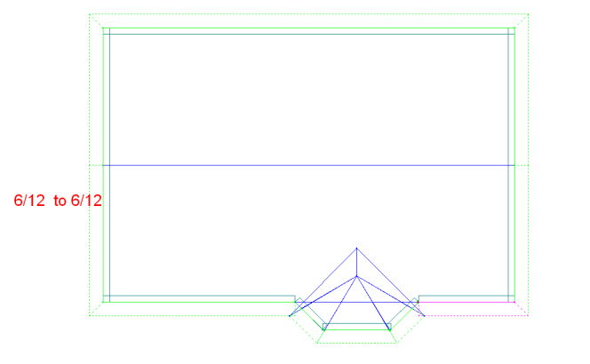
Now you
can add the roof areas and trusses.
Example (planes do not
match)
If the peak
of the bay window does not intersect the Back plane, you will be
required
to re-extend some planes; see below
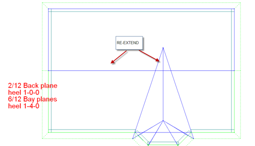
Results
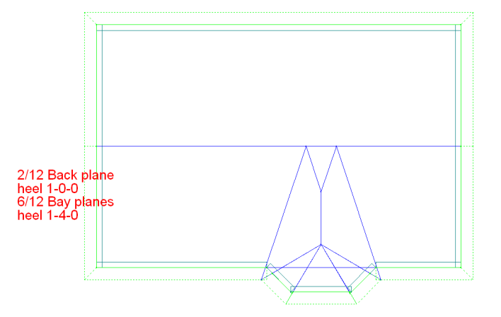
Now you can add the roof
areas and trusses.
Example (Bay wall height
is greater
than main house walls)
The Macro will open to the properties of the bay window

The macro will then detect that the plate heights are different and prompt the user a response

If you answer OK
or esc, the planes will be extended to the back plane.
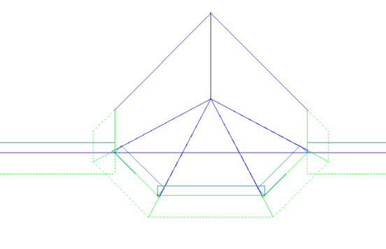
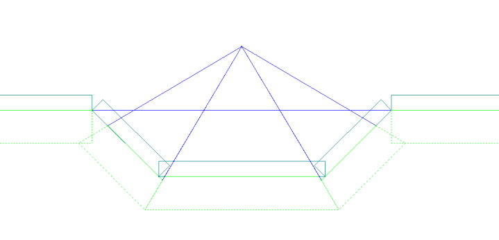
If the user
wishes to have the fascia match, the user will be required to calculate
the
plate difference and the additional extension of the overhang. In this case, the height was 1’ and the
pitch
was 6/12, therefore the 1’ / .5= 2’ => 1’ overhang
+ 2’ = 3’
The fascia
will match and you can add the roof areas and trusses.
Example (Bay wall height
is less than
main house walls)
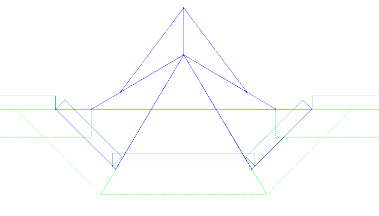
The front
and angle planes will come in correctly.
If the peak
of the planes is below the backing plane, you will have to re-extend
the
plane to the wall.
If the peak
of the planes is above the backing plane, i.e., bay pitches are greater
than
backing planes,you will have to re-extend the plane to the wall and
backing plane.
The program is robust enough to give the you the critical plane and peak point. This will make it very easy for the you to complete very complicated bay windows. All of the previous methods entry are still available.
Five Sided Bay Window Macro ![]()
First create intersecting and bay window walls in your layout. Next, select the Five sided Bay Window Macro from Macro Menu--> Roof Planes--> Five Sided Bay Window
Basic steps to follow after starting the macro are as follows:
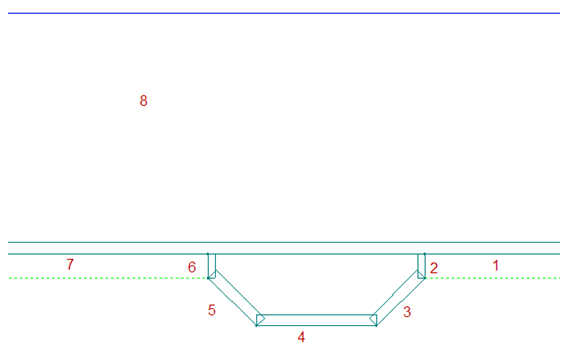
Select Walls and Back Plane
- You are prompted to select, with your mouse button, the Right intersecting wall
- You are prompted to select, with your mouse button, the Right side wall
- You are prompted to select, with your mouse button, the Right bay angle wall
- You are prompted to select, with your mouse button, Face bay wall
- You are prompted to select, with your mouse button, the Left bay angle wall
- You are prompted to select, with your mouse button, the Left side wall
- You are prompted to select, with your mouse button, the Left intersecting wall
- You are prompted to select, with your mouse button, the Back plane
Plane and Overhang Properties
Overhang Length - This is the overhang length around the bay. This value is needed to calculate the angle plane of the bay and to draw in the overhangs.
Symmetric Planes - Check symmetric planes, if the Side and Face Plane Properties are the same values. Please note that it is the your responsibility to match the back plane heel height or calculate the correct heel height to match the back plane pitch if it is different than the bay window pitches.
Side Plane Properties - The fields in these group boxes function just as the do in the standard plane properties dialogs.
Face Plane Properties - The fields in these group boxes function just as the do in the standard plane properties dialogs.
Set as Default Button - Clicking this button will set the current information in the dialog as the default information when this macro is run in the future.
Cancel Button - Clicking the Cancel button will return you to the main screen withoiut modifying the existing model.
OK Button - Clicking the OK button will accept the values in the dialog.
Changes to Edit Trusses
- Changes to Consolidation Settings
- The re-consolidation preset has been removed from the Gen Info--> Framing Members page.
- Changes have been made to the default re-consolidation behavior when starting Edit Trusses. Now when starting Edit Trusses the trusses are NOT re-consolidated and you are no longer prompted with the message, "Re-consolidate Trusses, Yes or No". By default existing truss consolidation groups are maintained. New trusses input since previous Edit Trusses run are consolidated into existing groups if possible, or create their new consolidation groups.
- If you need to re-consolidate trusses, select from the new Design Menu--> Reconsolidate All Trusses command or from the Design Toolbar hold down the Shift key and select the 'Edit Trusses' button.

- Set Truss Load Tolerance
- You are no longer prompted with the Truss Load Tolerance dialog when starting Edit Trusses.
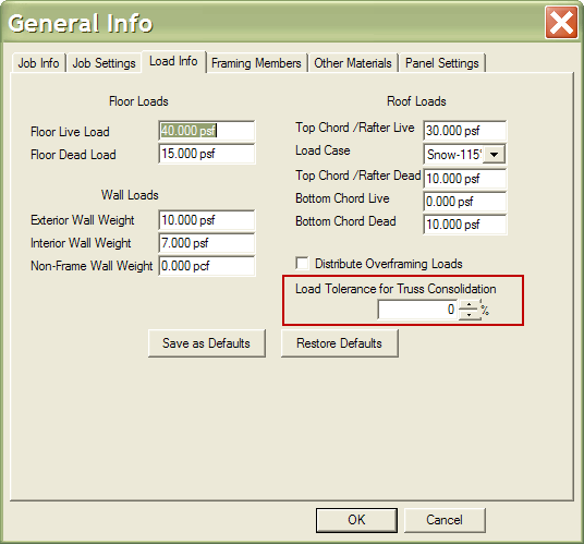
- The Truss Load Tolerance is now a preset
located in General Information--> Load Info tab--> Load Tolerance for Truss Consolidation.
You can also over-ride this preset and specify load tolerance for
truss consolidation if you Hold down
the Shift key +
 from the
Design Toolbar or select
from the new Design
Menu--> Reconsolidate All Trusses command
from the
Design Toolbar or select
from the new Design
Menu--> Reconsolidate All Trusses command
- Selecting Truss Types
- When you are in Edit Trusses, all trusses (standard trusses, gables, truss girders, valley trusses), roof and floor, are now selectable.
- Truss Labeling clean-up
Additional
functionality has been added to the Toggle Top Plate Elevation, ,
TPE will change the top plate elevation, as before, but now will shift
the
associated plane, and overhang. This functionality was designed to be
used
prior to adding any roof members. If the roof members are in place
prior to
using the top plate elevation toggle, it will be your
responsibility to
either delete the associated roof framing or adjust the associated
framing to
the appropriate elevation. Please note the single framed member will
require
that you shift the members by hand and the hip ends should be deleted
and
re-input at the appropriate elevation.
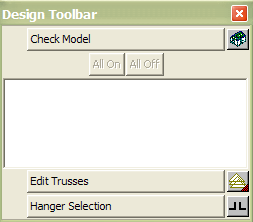
New Check Model Command has been added to the Design Toolbar
The Merge’s
Check Model command has been added to the top of the shortened Design
Toolbar. When selected the
Check
Model command verifies the integrity of the job as it is being built.
Joist and Truss Reference Line
An enhancement has been added in KeyBuild to the framing area dialog that gives the user the ability to set the reference line(s) on multiple trusses or joists.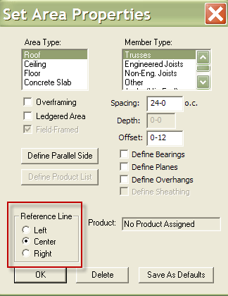
Z snap Cursor
When the user selects Z-snap mode the cursor changes to a +Z.
Master Hip Girder Option
The program now gives users the option to draw a Hip End without drawing the Master Hip Girder. When this option is chosen, neither the automatic Master Hip Girder nor any additional framing members beyond the back of the Master Hip Girder will be drawn. The program will only draw the hip girders and jack trusses. This would be used when the user needs to have complete control on the placement of the Master Hip Girder.

Right mouse click functionality in Framing Rules
An enhancement has been added to the New Framing Rules -->Stick Properties page that allows users to copy framing stick properties to new segments by right-clicking near the material drop-down arrow.Level added to Edit Trusses Dialog
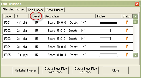
A new level column has been added to the Edit Trusses dialog. In this new column for each consolidation group the level number is displayed where the trusses in the consolidation group reside. If there are trusses in a single consolidation group from multiple levels all level numbers are displayed. If the user does not want to see this column, the column is controlled by change EDITTRUSS_LEVEL= 1 for ON or = 0 for OFF in GEN_INFO.TXT.
New Preset for Wall Re-frame Warnings
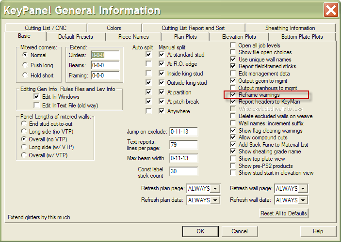
A new preset has been added to the Panel-->Gen Info-->Basic tab-->Reframe Warnings. The user now has the ability to disable the Re-frame warning. To turn off this warning, open Panel-->Gen Info-->Basic tab--> and uncheck the box labeled "Reframe Warnings".
