Raised Bottom Chord Bearing Condition
New functionality has been added that allows a raised bottom chord bearing condition by entering a new bearing type.
Create a new floor truss. In the General Information area, select a bearing type of "Raised BC".
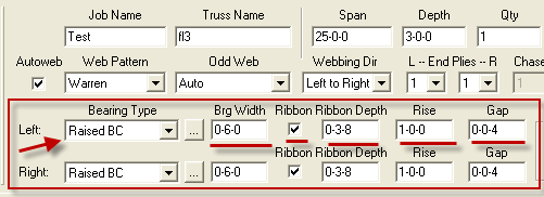
This then allows you to enter values for bearing width, ribbon and ribbon depth, the rise and the gap.
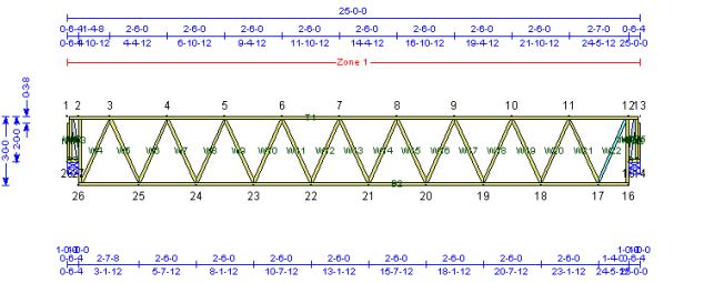
This an example of the resulting floor truss:
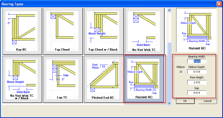
By pressing the ellipses in the bearing type you can also enter this information in the Bearing Types dialog.

When the bearing dialog appears, the raised BC bearing condition is the last bearing type. Select this and then input the desired values.
Save Load Combinations as Default
Previously, user defined load combinations could not be saved. Therefore, like values had to be entered for each truss. Now the information can be saved as the default, much like other presets can be saved. In addition, there is also a button to restore the load combination back to Keymark predefined values.
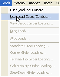
With your truss unlocked, choose Loads --> User Load Cases/Combos from the menu.
Select the Load Combinations tab. At this point you can modify the load combinations by expanding the tree and checking or un-checking combos.
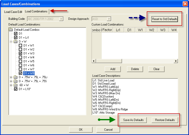
If you then press Save as Default (as indicated with the green arrow), the changes you made will be saved and used for the current truss and will be in effect until you change the preset again. You can restore the standard Keymark defaults by pressing the Reset to Std Defaults (as inidcated by the blue arrow). As normal you can press Restore Defaults if you do not want to save your most recent changes.
New Offset Dialog for Table Output
Currently the user cannot offset the image in the virtek output file. This enhancement allows control over where image is projecting on the tables.
Launch the Interface for Batch Output using the
![]() icon.
icon.
A dialog appears that allows you to select to enter offsets:
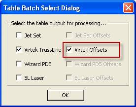
Once OK is pressed a dialog appears to allow entry of the offset values.
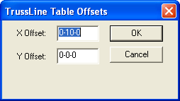
The offset are applied to the Virtek (or other table output) files.
Multiple Saws
This enhancement allows multiple saw file outputs to be selected when the saw is set up. This allows the saw to be changed after the batch has been run without rerunning the batch. This might be for scheduling purposes, because a saw is down, because a personnel resource that is not available, or to improve throughput.
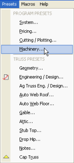
Go to your saw setup by going to Presets --> Machinery from the menu.
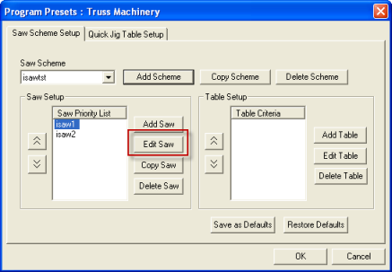
Select a scheme and edit a saw.
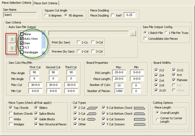
Note that you still see the choices for saws but there is now a check box next to each saw.
Select one or more saws. An output file will be created for each saw output selected.
!!Important!! The first saw in the list is the primary saw.
The order can be changed by highlighting the saw and using the up and down arrows to reorder the list. Again the first saw is the primary saw. In the example below Auto Omni is the primary saw and ISaw is the backup.
Note: if you want to continue to create only one saw file output as you do today, no changes are necessary.
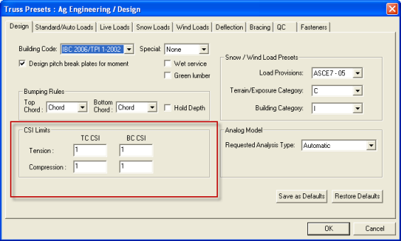
Additional Ag Truss Changes
This change allows designers to modify the CSI for agricultural trusses.
Selecting Joint Options by Number
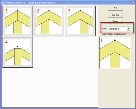
Options in the joint editor can now also be selected by the number from a drop down.
The following dialog is accessed by right clicking on a joint.
Please note that this dialog box is resizable and retains the size the next time you enter the dialog. Just move the mouse over a corner and drag to resize.
